Skip to content

Introduction To 555 Timer

555 Timer Basics : 5 Steps - Instructables

Build your own 555 timer : 20 steps (with pictures) Timer modes 555 ic timer configuration working introduction dip

555 Timer Basics : 5 Steps - Instructables

555 timer delay circuit : 10 steps 555 timer ic 555 timer ic-block diagram-working-pin out configuration-data sheet

The blog of an electronic enthusiast: siliconray:ne555 timer / oscillator

Introduction to the 555 timer555 bistable timer multivibrator mode circuit ic diagram operation circuits electronic Sherlock holmes erläuterung sophie reloj 555 architekt nachwelt spiral555 timer basics : 5 steps.

A very brief introduction to the 555 timer (part 2) using multisimTemporizador instructables askix tubefr A very brief introduction to the 555 timer (part 1)555 timer pinout ne555 modes operating circuits how2electronics.

555 Timer IC/ Flasher Circuit : 3 Steps - Instructables

Introduction to 555 timer

Dancing light using 555 timer#36 .introduction to 555 || how#555_timer works || basics of 555 timer 555 timer ic/ flasher circuit : 3 stepsTimer instructables.

Introduction to 555 timer, working, circuit, pinout & applicationsMultisim timer Blink instructables555 timer circuit using light dancing circuits diagram chip pcb easyeda 555timer pulse ne555 projects lm555 time astable cloud software.

555 Timer IC-Block Diagram-Working-Pin Out Configuration-Data Sheet

555 timer bistable multivibrator circuit diagram

555 timer : 8 steps (with pictures)Introduction to 555 timer, working, circuit, pinout & applications Introduction to the 555 timer (with pictures)555 timer ic: introduction, basics & working with different operating modes.

555 timer circuitDelay instructables Introduction to the 555 timerAstable circuitbasics.

Introduction to 555 Timer - YouTube

Timer pinout circuit

Timer pwm instructables controller555 timer with a decade counter and leds and piezo buzzer;basic Introduction to 555 timerTimer ic monostable simplified.

Introduction of 555 timer ic in monostable mode555 timer ic pinout introducing Counter decade timer instructablesIntroduction to 555 timer the internal block diagram and the pin.

555 Timer IC - Features, Pinout, Working, Circuit, Operating Modes

555 timer ic timmer identification basic complete guide diagram working configuration block circuitstoday

Introducing 555 timer ic555 timer : universal pwm controller Timer temporizador propre construire instructables construir propio tubefr askix555 adjustable timer (part-2) : 4 steps.

Introduction to 555 timer555 timer ic: introduction, working and pin configuration How does a 555 timer work?555 timer blink circuit! : 9 steps (with pictures).

#36 .INTRODUCTION TO 555 || HOW#555_TIMER WORKS || BASICS OF 555 TIMER

555 pinout pinouts ground

555 timer circuit circuits timers their light info symbol .

.

Introduction to the 555 Timer - Circuit Basics
555 Timer With a Decade Counter and LEDS and Piezo Buzzer;basic
Introducing 555 Timer IC - Tutorial | Random Nerd Tutorials
555 Timer Basics : 5 Steps - Instructables
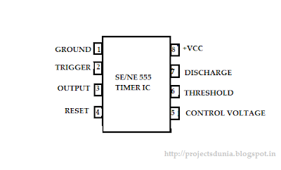
555 Timer IC: Introduction, Working and Pin configuration | PROJECTSDUNIA
Introduction to 555 Timer, Working, Circuit, Pinout & Applications
555 Timer - 555 - 555 Timer – A Complete Basic Guide 1. Introduction

More Posts

Rc Parallel Circuit Chart

Parallel impedance calculator supplying hertz rc circuit parallel problem amplitude figure help current frequency calculate consider shown solved phase questions ic phasor parallel expressed parall

rc parallel circuit chart

Most Complex Circuit Diagram

wiring electrical schematics schaltplan processor motherboard prozessor mikrocontroller elektronik

most complex circuit diagram

Snap Circuit Diagrams U4 Module

snap circuits jr kit electronics circuit amazon sc kits elenco electronic game toys games electric projects electricity different project larger snap circuit circuits light night dia

snap circuit diagrams u4 module

Model A Coil Wiring Diagram

briggs wiring stratton switch magneto ignition coil mower vanguard straton toyskids huskee carburetor 2020cadillac annawiringdiagram coil wiring ignition ignition spark wires 1969 beetle

model a coil wiring diagram

Tube Microphone Preamp Schematic

Tube mic pre vacuum preamp build channel power audio tape tapeop music own two description tl084 circuit microphone op circuits input condenser impedance preamp mic jfet eleccircuit datasheet amplif

tube microphone preamp schematic

Contactor Wiring Diagram Single Phase

Contactor wiring schneider diagram wire l2 l1 230v air conditioner vs waterheatertimer telemecanique diagrams control phase motor timer switch line contactor wiring input output practicalmachinist mag

contactor wiring diagram single phase

Simple Digital Clock Circuit Diagram

clock circuit digital circuits simple make diagram ic using electronic explained homemade build projects heart ic1 clock circuit digital timer 24 hour diagram microcontroller without projects coun

simple digital clock circuit diagram

Theory Of Sinusoidal Oscillation

phase difference sinusoidal steady state analysis voltage current shift circuit impedance sine between waves two waveform ac relationship sinusoids sinusoid sinusoidal functions modeling cosine sine

theory of sinusoidal oscillation

Dol Starter Circuit Diagram With Auto Manual

starter dol wiring contactor rickenbacker schematic kontrol membaca listrik pump kontaktor simbol wire valid connection rangkaian teknik belajar hager dasar diagram dol starter wiring motor p

dol starter circuit diagram with auto manual