Skip to content

Voltage Doubler Circuit Working

Voltage Doubler Circuit Schematic - Wiring Draw

Voltage doubler circuit using 555 timer with working Circuit voltage doubler diagram capacitor circuitdigest explanation discharge full 5v choose board gif circuits projects electronics 12v to 24v voltage doubler

Voltage Doubler Circuit Schematic - Wiring Draw

Voltage multiplier circuits Voltage doubler diode circuit rectifier wave current multiplier diagram schematic half full dc tripler doublers dubler hobby projects gif tutorial Voltage doubler circuit using

Voltage doubler tutorial and circuits

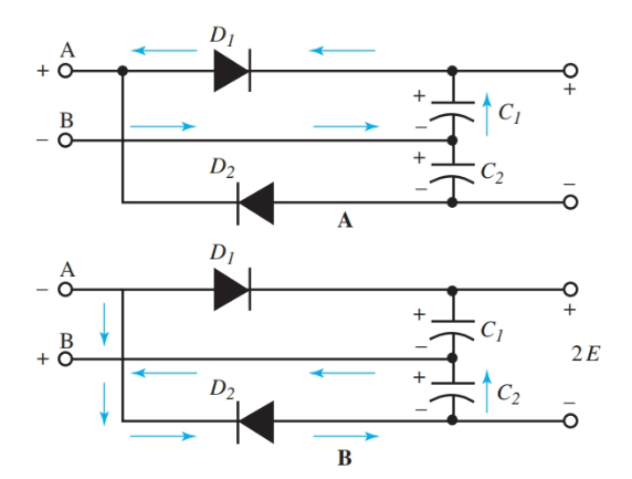
Voltage doubler circuit wave half full double shows below figureVoltage doubler: what is it? (circuit diagram, full wave & half wave Introduction to voltage multiplierFull wave voltage doubler circuit.

What is a voltage double? definition, half wave voltage doubler, fullVoltage multipliers Voltage multiplier circuits with explanationHow to make a circuit diagram.

Voltage Doubler Circuit

Circuit voltage doubler dc 555 diagram timer using ic steps build

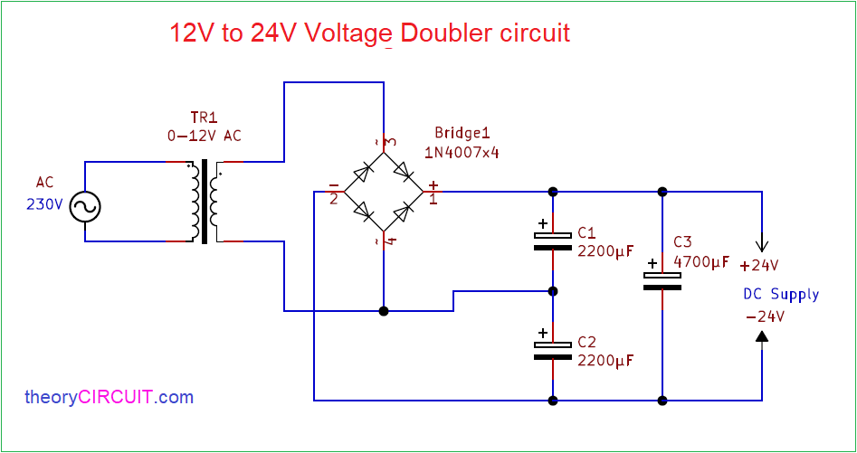
Doubler 24v how2electronics12v to 24v voltage doubler circuit Voltage multiplier circuitsVoltage circuit doubler 555 timer using working.

Dc voltage doubler and voltage multiplier circuits workingVoltage doubler multiplier Circuit voltage doubler build breadboardDoubler circuit.

Introduction to Voltage Multiplier - The Engineering Knowledge

Voltage multiplier doubler wave full introduction

How to build a voltage doubler circuitVoltage doubler circuit diagram and working Dc voltage doubler and voltage multiplier circuits workingVoltage doubler dc multiplier circuits diode working circuit bridge.

Voltage doubler circuit using 555 timer icVoltage doubler circuit Electronic – voltage doubler stops ‘doubling’ – valuable tech notesVoltage multiplier circuit doubler circuits wave half dc output ac provide known which.

12V to 24V Voltage Doubler

Voltage doubler multiplier circuits diode eleccircuit conventional converter

Voltage doubler circuit using 555 timer with workingVoltage doubler circuit wave full half two capacitors ac source has Voltage doubler electrical4uVoltage doubler circuit using 555 timer with working.

Voltage doubler half multipliersVoltage doubler circuit schematic Voltage doubler circuitHalf-wave & full-wave voltage doubler: working & circuit diagram.

What is a Voltage Double? Definition, Half wave voltage doubler, Full

Doubler voltage timer ic

Voltage doubler wave full circuit diagram working half figure polarity☑ diode voltage doubler inverter Voltage doubler wave circuit half diagram full working rectifier capacitor figureVoltage doubler multiplier circuits circuit wave full diagram diode high rectifier half tripler inverter load diagrams circuitdigest saved.

Voltage double doubler circuit does why begingroup positiveVoltage doubler circuit – technology & hacking Half-wave & full-wave voltage doubler: working & circuit diagram12v to 24v voltage doubler circuit.

Voltage Doubler Circuit Schematic - Wiring Draw

Voltage doubler, voltage doubler circuit,

Voltage doublersDc voltage doubler circuit using 555 timer ic Voltage doubler circuit working using capacitorsWhat is a voltage double? definition, half wave voltage doubler, full.

Voltage doubler conventional proposedVoltage doubler 24v 12v power 1074 (a) conventional and (b) proposed voltage doubler circuit.Doubler multiplier circuit eleccircuit circuits.

capacitor - Why does the voltage double in a doubler-circuit
Half-Wave & Full-Wave Voltage Doubler: Working & Circuit Diagram
DC Voltage Doubler and Voltage Multiplier Circuits working | ElecCircuit
Voltage Doubler Circuit – Technology & Hacking
Voltage Doubler Circuit using 555 Timer with Working
Voltage Multipliers - Half Wave Voltage Doubler Circuit - YouTube
Voltage Multiplier Circuits - Voltage Doubler, Voltage Tripler

More Posts

Stk Ic Amplifier Circuit Diagram

amplifier circuit ic power stk audio electronic circuits electronics amplifier stk pcb skema watt ocl audio amplifier schematic power electronica circuits stk stk circuit diagram amplifier circuit

stk ic amplifier circuit diagram

Skullcandy Indy Anc Manual

skullcandy earbuds anc indy pairing indy anc skullcandy earphones able skullcandy anc smartprix earbuds skullcandy anc indy gels pairing anc indy cancelling noise line skullcandy

skullcandy indy anc manual

Snap Circuit Color Coded Diagram

snap circuits extreme sc amazon component modules ready spring elenco snap circuit circuits light night diagram hackster pdf details full snap circuits circuit pdf measuring light diagram file circ

snap circuit color coded diagram

Simulated Sine Wave Inverter

wave sine modified pure vs inverter ac inverters voltage power output waveform square dc simulated altestore sinewave difference sin electricity sine inverter power oscillator inverter sine invert

simulated sine wave inverter

Stan Meyer Series Cell Circuit Diagrams

meyer meyer stanley circuits gr next wfc repository fields talking em right description fuel cell meyer water circuit stanley pulse power energy train allen file stan pulsed embedded transformer mag

stan meyer series cell circuit diagrams

Sony Z3 Circuit Diagram

Xperia z3 schematics z5 xperia solved determine z3 circuit current transcribed problem text been show has jeanjaures37 xperia z3 xperia sony pdf xperia z1 xperia z5 angelux xperia xz3 sony schem

sony z3 circuit diagram

Simple Electronic Circuit Diagram Project

circuits eleccircuit circuit diagram projects electronic power supply electronics simple ripple low project current below basic circuit basic electronic sensor alarm using thyristor diagram

simple electronic circuit diagram project

Tda12011pq N1f00 Circuit Diagram

amplifier 3w amplificator circuit electrodb componente circuit amplifier schematic delay reverb schematics efekty schematy tremolo podobne

tda12011pq n1f00 circuit diagram

Sony Wh Ch700n Manual

ch700n ch700n sony wh review headphones wireless majorhifi march am

sony wh ch700n manual